WARNING SYSTEMS
Chime Wiring Diagram for Nissan Maxima SV 2014
 https://portal-diagnostov.com/license.html
Automotive Electricians Portal FZCO
Automotive Electricians Portal FZCO
https://portal-diagnostov.com/license.html
https://portal-diagnostov.com/license.html
Automotive Electricians Portal FZCO
Automotive Electricians Portal FZCO
List of elements for Chime Wiring Diagram for Nissan Maxima SV 2014:
- (behind right side of dash) m57
- (w/ information display) unified meter control unit
- 10j
- 11p
- 12m
- 24g
- 24j
- 57g
- Air bag diagnosis sensor unit (under rear of center console)
- B1 m6
- B12
- B201
- B7 (under driver's seat)
- Bat (f/l)
- Bat bcm fuse
- Bcm (body control module) (behind instrument cluster)
- Brake ind
- Buzzer
- Can-h
- Can-l
- Card sw1
- Combination meter
- Combination switch (lighting & turn signal switch)
- Computer data lines system
- Dr door sw
- E30
- Fob in sw 1
- Fuse & fusible link box (left front of engine compt)
- Fuse 10a
- Fuse block (j/b) (lower left side of dash)
- Fusible link h 40a
- Gnd
- Gnd 1
- Hot at all times
- Hot in on or start
- Input 1
- Input 2
- Input 3
- Input 4
- Input 5
- Instrument cluster system
- Intelligent key warning buzzer (behind left end of dash)
- Joint connector b04 (left side of luggage compt)
- K-line seat belt reminder m35
- Key slot
- Left front door switch (left "b" pillar)
- Left seat belt buckle switch (under driver's seat)
- Lh buckle sw input b9
- M1 e30
- M16
- M17
- M18
- M19
- M21
- M24
- M57 (behind right side of dash)
- M6 b1
- M79 (left center of dash)
- Output 1
- Output 2
- Output 3
- Output 4
- Output 5
- Parking brake switch (on brake pedal bracket)
- Pnk
- Red
- Seat belt ind
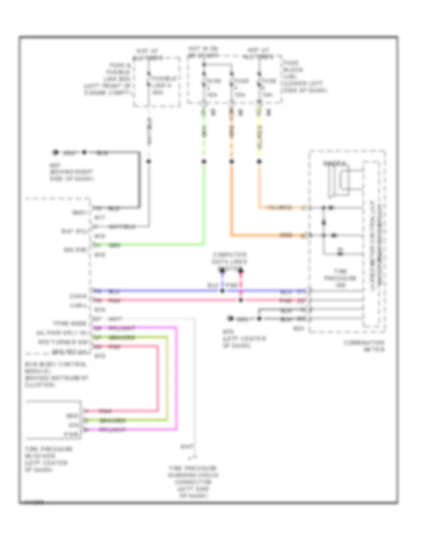
Tire Pressure Monitoring Wiring Diagram for Nissan Maxima SV 2014
List of elements for Tire Pressure Monitoring Wiring Diagram for Nissan Maxima SV 2014:
- (w/ information display) unified meter control unit
- 12m
- A/l pwr sply 5v
- Bat (f/l)
- Bcm (body control module) (behind instrument cluster)
- Buzzer
- Can-h
- Can-l
- Combination meter
- Computer data lines system
- Fuse & fusible link box (left front of engine compt)
- Fuse 10a
- Fuse block (j/b) (lower left side of dash)
- Fusible link h 40a
- Gnd
- Gnd rf2 a/l
- Gnd1
- Hot at all times
- Hot in on or start
- Ign (f/b)
- M16
- M17
- M18
- M19
- M24
- M57 (behind right side of dash)
- M79 (left center of dash)
- Pnk
- Pwr
- Rf2 turner sig
- Sig
- Tire pressure ind
- Tire pressure receiver (left center of dash)
- Tire pressure warning check connector (left side of dash)
- Tpms mode

 Čeština
 Dansk
Dansk Deutsch
 Ελληνικά
 English
 Español
 Suomi
Suomi Français
 Français
 עברית
עברית Hrvatski
 Magyar
 Italiano
 日本語
日本語 한국어
한국어 Nederlands
 Polski
 Português
 Português
 Română
 Русский
 Slovenčina
 Slovenščina
 Svenska
 Türkçe
 中文 (中国)