WARNING SYSTEMS
Warning System Wiring Diagrams for Nissan Quest GXE 1995
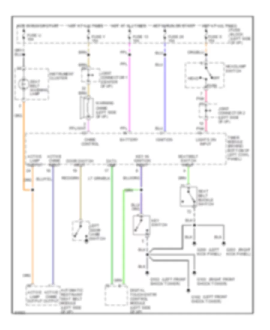
List of elements for Warning System Wiring Diagrams for Nissan Quest GXE 1995:
- (left
- (left front
- (right
- (right front
- Active chime input
- Active chime output
- Active lamp output
- Automatic restraint seat belt module (left side of i/p)
- Battery
- Chime (left side of i/p)
- Chime control
- Data line
- Digital touch entry control module (left side of i/p)
- Door switch input
- Fuse 13 10a
- Fuse 20 10a
- Fuse block (left side of i/p)
- Fuse s 15a
- Fuse u 10a
- Fuse y 15a
- G102 shock tower)
- G103 shock tower)
- G200 kick panel)
- G203 kick panel)
- Head
- Headlamp switch
- Hot at all times
- Hot in run or start
- Ignition
- Instrument cluster
- Joint connector 1 (center of i/p)
- Joint connector 2 (left side of i/p)
- Key in ignition input
- Key switch
- Left door jamb switch
- Lights on input
- Off
- Park
- Pnk
- Seat belt buckle switch
- Seat belt warning lamp
- Seatbelt switch input
- Timer module (behind bottom of left cowl panel)
- Warning
 Čeština
 Dansk
Dansk Deutsch
 Ελληνικά
 English
 Español
 Suomi
Suomi Français
 Français
 עברית
עברית Hrvatski
 Magyar
 Italiano
 日本語
日本語 한국어
한국어 Nederlands
 Polski
 Português
 Português
 Română
 Русский
 Slovenčina
 Slovenščina
 Svenska
 Türkçe
 中文 (中国)
 English