WARNING SYSTEMS
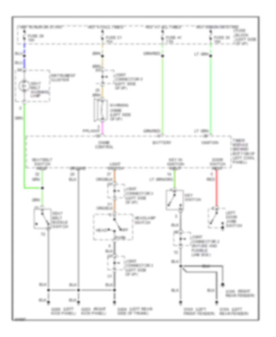
Warning System Wiring Diagrams for Nissan Quest GXE 1996
List of elements for Warning System Wiring Diagrams for Nissan Quest GXE 1996:
- (left
- (left rear
- (right
- Battery
- Chime (left side of i/p)
- Chime control
- Door switch input
- Fuse 21 15a
- Fuse 29 10a
- Fuse 30 10a
- Fuse 41 7.5a
- Fuse block (left side of i/p)
- G100 front fender)
- G104 rear fender)
- G105 rear fender)
- G200 kick panel)
- G203 kick panel)
- G404 side of trunk)
- Ground
- Head
- Headlamp switch
- Hot at all times
- Hot in run or start
- Ignition
- Instrument cluster
- Joint connector 2 (in fuse and fusible link box)
- Joint connector 3 (left side of i/p)
- Joint connector 5 (left side of i/p)
- Key in ignition input
- Key switch
- Left door jamb switch
- Light switch
- Off
- Park
- Red
- Seat belt buckle switch
- Seat belt warning lamp
- Seatbelt switch input
- Timer module (behind bottom of left cowl panel)
- Warning
 Čeština
 Dansk
Dansk Deutsch
 Ελληνικά
 English
 Español
 Suomi
Suomi Français
 Français
 עברית
עברית Hrvatski
 Magyar
 Italiano
 日本語
日本語 한국어
한국어 Nederlands
 Polski
 Português
 Português
 Română
 Русский
 Slovenčina
 Slovenščina
 Svenska
 Türkçe
 中文 (中国)
 English