WARNING SYSTEMS
Chime Wiring Diagram for Subaru Forester XT Premium 2011
 https://portal-diagnostov.com/license.html
Automotive Electricians Portal FZCO
Automotive Electricians Portal FZCO
https://portal-diagnostov.com/license.html
https://portal-diagnostov.com/license.html
Automotive Electricians Portal FZCO
Automotive Electricians Portal FZCO
List of elements for Chime Wiring Diagram for Subaru Forester XT Premium 2011:
- B186
- B279
- B280
- B281
- B38
- B52
- B99
- Body integrated unit (behind center of dash)
- Buzzer
- Can transeiver & receiver
- Clock
- Combination meter
- Computer data lines system
- Door warning light ind
- Drive circuit
- Fuse & relay box (f/b) (left kick panel)
- Fuse 10a
- Fuse 15a
- Fuse 7.5a
- Gb-9 (behind left rear quarterpanel)
- Hot at all times
- Hot in on or start
- Hot w/ ig2 relay energized
- I/f
- I102
- I84
- Key warning switch (left side of dash)
- Left front door switch (left "b" pillar)
- Light ind warning seat belt
- Main fuse box (m/b) (left side of engine compt)
- Micro computer
- Passenger's seat belt warning light ind
- Pnk
- Power distribution system
- R167
- R168
- Red
- Remote engine start control module (left side of dash)
- Seat belt switch (driver's seat belt buckle)
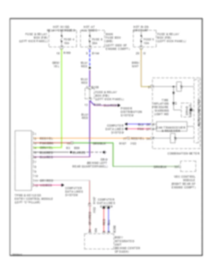
Tire Pressure Monitoring Wiring Diagram for Subaru Forester XT Premium 2011
List of elements for Tire Pressure Monitoring Wiring Diagram for Subaru Forester XT Premium 2011:
- (left side of engine compt)
- B144
- B158
- B280
- B99
- Body integrated unit (behind center of dash)
- Can transceiver & receiver
- Combination meter
- Computer data lines system
- Drive circuit
- Fuse & relay box (f/b) (left kick panel)
- Fuse 4 10a
- Fuse 5 10a
- Fuse 8 20a
- Gb-9 (behind left rear quarterpanel)
- Hot at all times
- Hot in on or start
- Hot w/ ig2 relay energized
- I/f
- I102
- I84
- Main fuse box (m/b)
- Micro computer
- Pnk
- Power distribution system
- R167
- R167 i102
- R168
- Red
- Tire inflation pressure warning light ind
- Tpms & keyless entry control module (left "c" pillar)
- Vdc control module (right rear of engine compt)

 Čeština
 Dansk
Dansk Deutsch
 Ελληνικά
 English
 Español
 Suomi
Suomi Français
 Français
 עברית
עברית Hrvatski
 Magyar
 Italiano
 日本語
日本語 한국어
한국어 Nederlands
 Polski
 Português
 Português
 Română
 Русский
 Slovenčina
 Slovenščina
 Svenska
 Türkçe
 中文 (中国)